

RIMOND was the Design & Build partner for the Garden Pavilion at Milan Design Week 2026, leading executive design and construction. Commissioned by the Uzbekistan Art and Culture Development Foundation and designed by Kulapat Yantrasast, principal of WHY Architecture, the project explores the dialogue between tradition and contemporary design, reflecting on the regeneration of the Aral Sea region.
We interviewed the engineering experts from RIMOND team to explore the structural thinking behind the project.
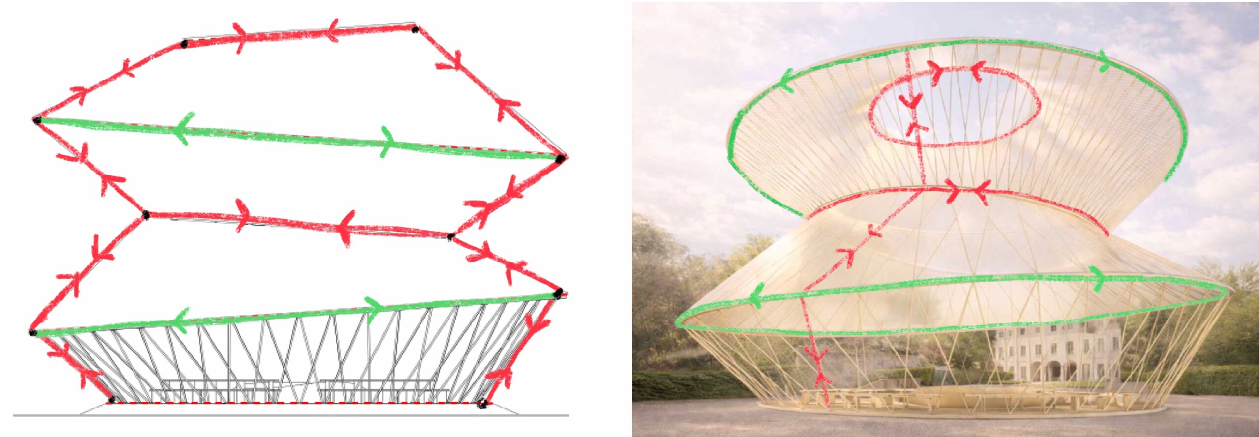
The pavilion is inspired by the traditional yurt: how is this architectural reference reflected in its structural behaviour?
GMP: The traditional yurt is a remarkably efficient structure from a structural standpoint. It is able to cover a circular space using a lightweight, demountable system based on a clear set of principles: a circular perimeter lattice, a series of radial roof elements converging towards a central ring, and a system of tension bands that prevent the structure from spreading outward. In essence, the yurt works through a balance between compression and tension. The inclined elements transfer loads towards the perimeter, while the circular rings and tension bands control horizontal thrust and stabilize the system.
In the pavilion celebrating Uzbek culture, exhibited at Palazzo Citterio in Milan, this logic is reinterpreted in a contemporary way through a steel structure. The reference to the yurt is not only formal, but also structural: the circular geometry, concentric rings, radial and diagonal members, and the hierarchy between primary and secondary elements all reflect the behaviour of the traditional system.
From a structural perspective, vertical loads are mainly carried by a system of inclined and radial members working predominantly in compression, transferring forces to the rings and the perimeter. The circular rings play a key role in bracing and stabilization: depending on their position, geometry, and loading conditions, they can be subject to both compression and tension, contributing to closing the structural system and controlling the horizontal forces generated by the inclined elements.
A similar behaviour can be observed under horizontal loads, particularly wind. In this case, the response is not limited to a planar scheme but involves the entire three-dimensional system. The members of the perimeter lattice alternately work in compression and tension, while the rings also participate in redistributing forces, both locally and globally. It is precisely this interaction between members and rings that allows the structure to achieve equilibrium and stiffness, in a way that closely resembles the behaviour of traditional yurts.
Of course, in our case this is not a timber or textile yurt, but a steel pavilion designed to meet contemporary requirements in terms of safety, stiffness, regulations, and assembly. However, the structural analogy remains clear: as in the yurt, the system works through the collaboration of compression elements, tension elements, and continuous rings.
The structural analysis process was therefore not only about verification, but also about interpreting this complex geometry as a coherent three-dimensional structural organism, where each element contributes to the overall equilibrium.
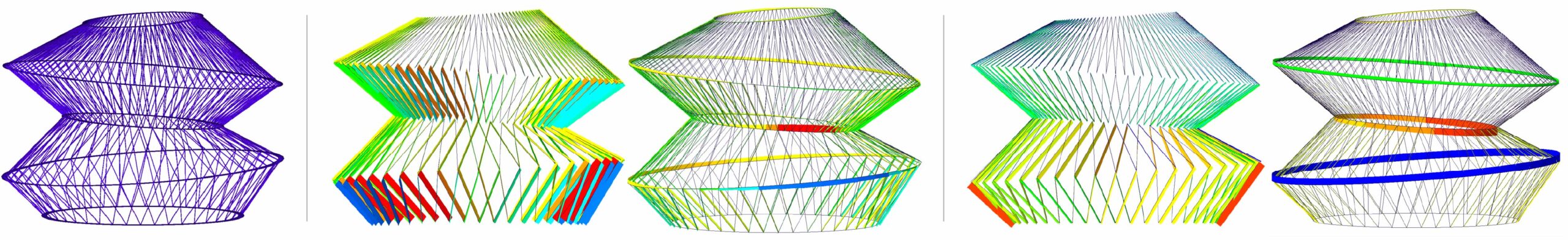
From left to right: FEM model; axial forces due to gravity loads for trusses only and for the full model; axial forces due to wind load for trusses only and the full model.
What was the main challenge in the structural analysis?
GMP: One of the main challenges was identifying the most critical loading conditions for a lightweight, three-dimensional structure with a complex geometry. In systems like this, it is not sufficient to apply wind loads along a few conventional directions: the structural response is highly dependent on the orientation of the horizontal action relative to the geometry of the rings and radial members.
For this reason, a significant part of the structural verification focused on determining the most critical wind direction in terms of overall resistance and stability. Wind loads were applied parametrically to the structural members, allowing the direction of incidence to be continuously varied and the effects of each configuration to be evaluated across the entire system.
To support this process, a parametric computational model was developed in Rhino/Grasshopper, integrated with the Karamba3D plugin, enabling a direct link between the pavilion geometry and the finite element model. This approach made it possible to efficiently manage multiple load scenarios, moving beyond a limited set of discrete cases and allowing for a more comprehensive understanding of the structural behaviour.
To identify the most severe configuration, Octopus, a multi-objective optimization plugin for Grasshopper was also used. In this context, it helped explore different wind directions and identify those that maximized the utilization of the structural members. The objective was not simply to find the maximum load on a single element, but to understand the conditions under which the structure, as a whole, was most critically stressed.
Another key challenge was the structure’s sensitivity to second-order effects. The pursuit of lightness and material efficiency inevitably leads to slender members, which can be significantly affected by deformation. For this reason, the analysis had to consider not only the equilibrium of the structure in its initial configuration, but also in its deformed state, accounting for the amplification of stresses due to geometric nonlinearity.
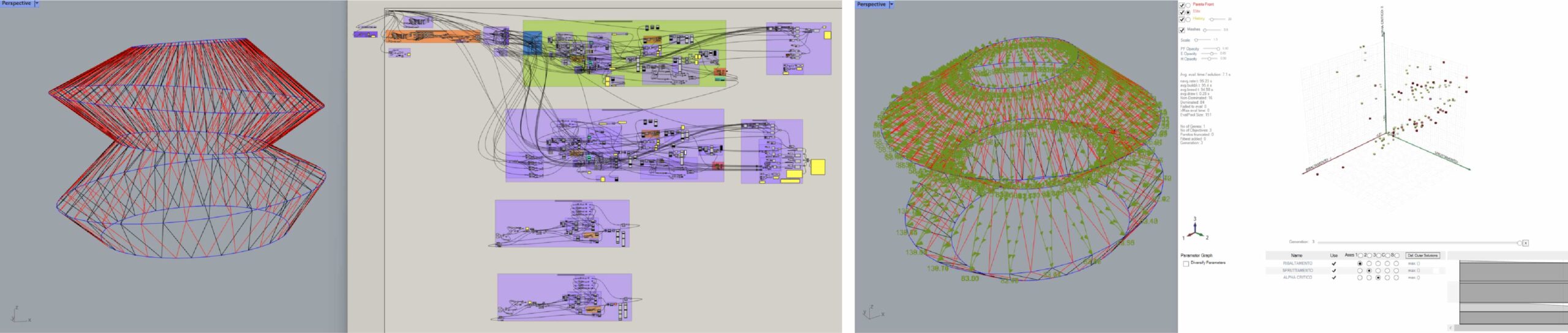
From left to right: Rhinoceros / Grasshopper model; multi-objective optimization tool to search for the most severe wind direction for structural stability and resistance.
How did the digital strategy bridge the gap between the preliminary design and the high-precision requirements of DfMA for the steel structure?
LP: While the architectural concept and preliminary geometry were established, translating them into a buildable steel structure required a workflow that could absorb constant refinement. Every technical adjustment (from plate thicknesses and member sections to the specific dimensions of the connection rings) directly impacted the global geometry. To resolve this without compromising the architectural intent, we developed a Wireframe Model in a parametric environment (Rhino3d / Grasshopper) as the intermediary between design and fabrication.
This strategy allowed us to treat the preliminary design as a set of governing rules rather than a static shape. By focusing on a high-fidelity wireframe first, we could “optioneer” the constructive details while automatically adjusting inclinations and member lengths as ring profiles evolved. In parallel, the same algorithm was generating the geometry for the global structural analysis, removing the unnecessary eccentricities. The digital workflow ensured that even as we solved for complex intersections and varying support counts across adjacent levels, the structural logic remained aligned with the original aesthetic.
The real power of this approach lay in the automation of the Detail Model: the script could generate the fabrication data for each and every iteration and change in the wireframe model. When the reference geometry was actually consolidated, the script generated the final fabrication data, including automated and optimized nesting for pipes and plates. Each component is identified by a specific ID plate to maintain total traceability. This allowed us to move from a fluid preliminary model to a high-precision set of shop data, facilitating a controlled pre-assembly in the shop and a successful top-to-bottom installation in the constrained environment of the Palazzo Citterio courtyard.
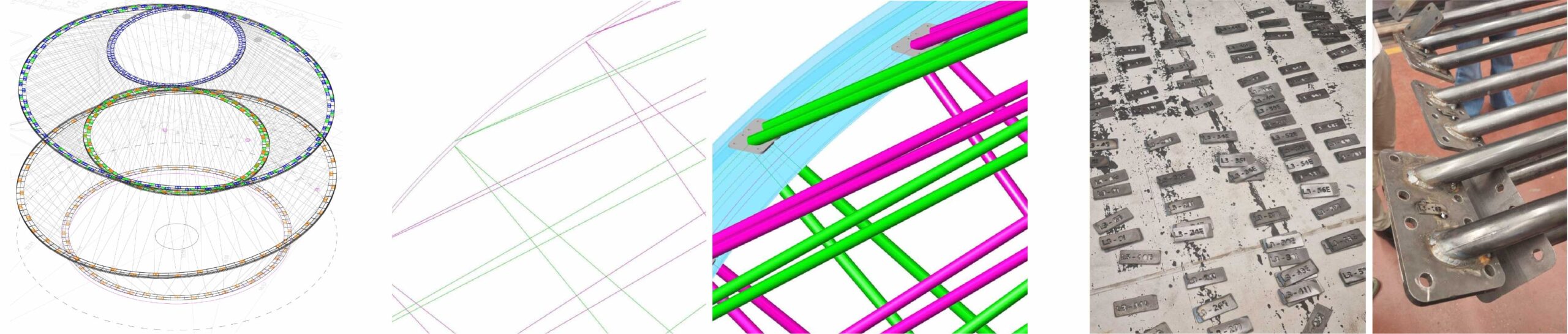
From left to right: global wireframe geometry, comparison between theoretical wireframe model and fabrication model and ID tagging of steel components.
In a project with geometric complexity and hundreds of unique components, how did the team manage assembly tolerances and ensure a seamless installation on-site?
LP: Managing tolerances in a complex steel structure such as this one requires a hybrid approach that balances digital perfection with physical verification. While our parametric model provided high-precision coordinates and laser-engraved unique IDs for every component to eliminate sorting errors, we recognized that theoretical geometry often meets challenges during full-scale fabrication, especially given the lightness and slenderness of the elements forming the structure itself.
To mitigate this, we implemented a shop-to-site feedback loop. The structure was pre-assembled in the shop level by level, stacking them in couples to verify the coherence of the interface rings. Rather than forcing the steel to match a rigid digital twin, we designated “strategic components” to be cut to size based on the as-built condition during this shop assembly. This ensured that any cumulative tolerances were absorbed before the structure left the factory floor, guaranteeing a perfect fit once on-site.
This rigorous pre-assembly logic was fundamental to our installation strategy at Palazzo Citterio. Because the courtyard offered extremely tight spatial constraints, we reversed the typical construction sequence, opting for a top-to-bottom assembly. The four levels were shipped as verified sub-assemblies, assembled and lifted into place, starting from the highest tier. This “reversed” execution was only possible because the digital strategy and shop pre-assembly had already resolved the geometric conflicts, allowing for a swift, surgical installation that respected both the historic context and the technical complexity of the deconstructed yurt design.
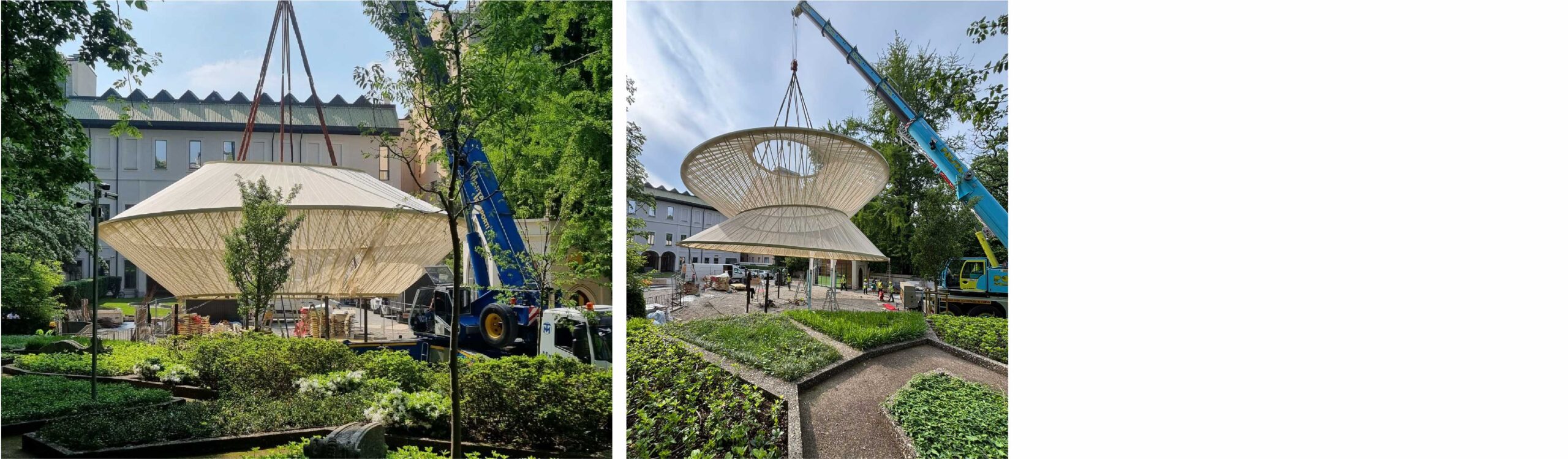
From left to right: the 2 top levels being lifted and then, in the next phase, the 3 top levels being lifted to assemble the lowest one.